23 Jul 2024
From concept to reality: Inside Cambridge Mechatronics’ SMA actuator design and development cycle
By Robin Eddington, Head of Product Design
As the leader in the development of Shape Memory Alloy (SMA) actuators, Cambridge Mechatronics Ltd. prides itself on an innovative but meticulous engineering design cycle that enables the creation of compact, high-performance actuators for smartphone cameras and other applications. Our process is designed to create actuators with unique properties that other technologies cannot deliver whilst meeting industry-standard reliability. Using our SMA Module Tilt OIS product as an example project, we provide here a short guide on the standard design stages we follow to bring our innovative product designs to life.
Phase 1: Product specification definition
The first step in our design cycle is to define the product specifications. This phase ensures that we have clear goals and understand what we need to achieve to make our product both desirable and viable. Key activities include:
Understanding user and customer requirements
We engage with our client-facing team, who spend significant time understanding market needs. They talk to potential customers, which are typically OEMs or manufacturers who are one or two levels removed from the end user (smartphone users in the case of Module Tilt OIS), to understand their specific requirements. This helps us tailor our product(s) to meet the needs of our customers. It’s essential for us to differentiate between the end user’s requirements and the immediate customer's specifications to ensure that the final product aligns with the market demands.
Performance analysis
We conduct studies to determine performance requirements. For example, we collected gyroscope (shake motion) data from mobile phones during activities like running and walking to understand the compensation angles our actuators need to achieve for effective image stabilisation.
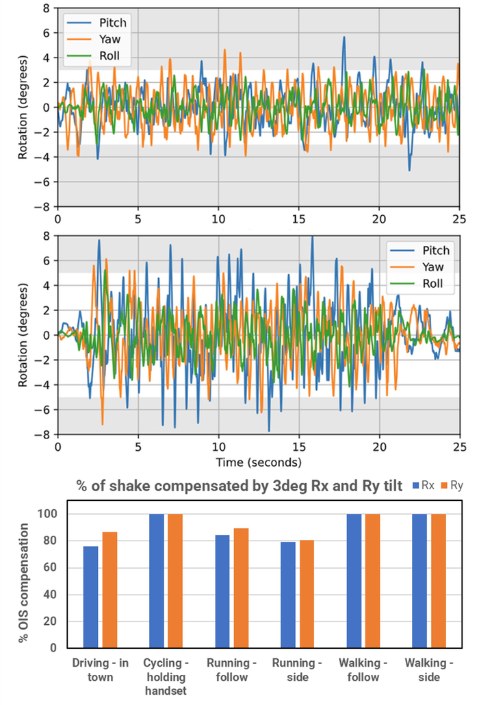 Figure 1: Gyroscope data showing motion amplitude from walking (top) and running (middle). %OIS compensation for an SMA Module Tilt OIS design to compensate for 3 degrees (bottom).
By analysing the performance under real-world conditions, we ensure that our actuators can handle typical user movements, providing clear and stable images in a wide range of conditions.
Competitor analysis
Analysing competitors’ products helps us set benchmarks and identify areas where we can provide a user benefit, ensuring our products meet or exceed market standards. Understanding what competitors are achieving allows us to set realistic performance goals and to find opportunities to surpass current market offerings.
Phase 2: Concept generation
Once we have a clear specification, we move to the second phase in our design cycle which is to generate a range of design concepts. This involves:
Reviewing past work
We review previous projects and other actuators that achieve similar functions to inspire innovative ideas. This helps us refine our concepts and generate well-informed solutions. Learning from past successes and failures allows us to build on proven ideas while avoiding known pitfalls.
Functional breakdown
Breaking the product into functional areas allows us to brainstorm solutions for each function. This structured approach ensures comprehensive coverage of a wide range of potential solutions whilst also providing a strong foundation for our Intellectual Property (IP) protection. For instance, we might separately address how to move the actuator, how to support and constrain it, and how the driver chip is integrated for power and control.
Generating concepts
For developing several sufficiently different concepts, we generate options to meet the functions of the product and brainstorm with a larger group of creative engineers. Cambridge Mechatronics has a lot of engineers experienced in the design of SMA actuators and using this collaborative approach with a range of engineering backgrounds helps in generating diverse ideas, ensuring that we consider multiple potential solutions before narrowing down to the best ones.
Concept analysis and evaluation
In this stage, we evaluate the generated concepts against the initial specifications. This provides a more detailed understanding of the pros and cons of the front-running concepts through simple calculations, more complex math models, and Finite Element Analysis (FEA) simulations.
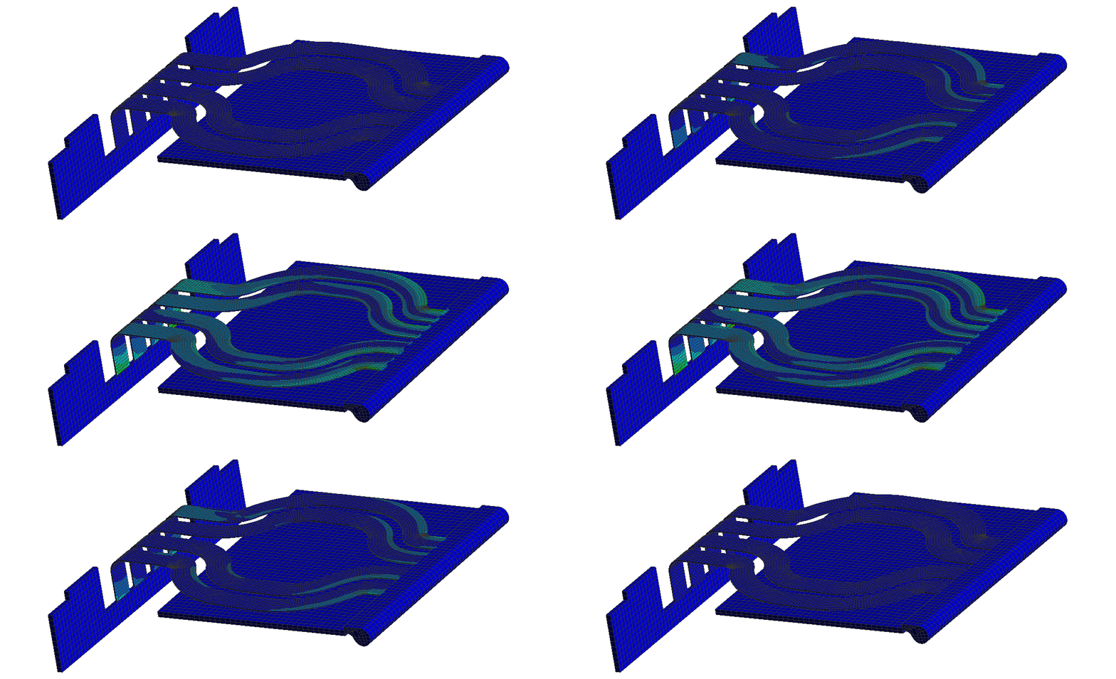 Figure 3: Example of flexible printed circuit (FPC) stiffness analysis showing stress changes in the structure through actuator stroke.
Here we call on experience and tools particular to SMA actuator design which, for example, enable us to predict how much stroke we can extract from the SMA wire for a given design, how the control system will perform depending on factors such as friction, how to integrate the design with our driver ICs and assessment of the reliability of designs from the perspective of the SMA wire. We analyse the feasibility of each concept, considering additional factors such as manufacturability, cost, size, performance, and reliability risks common to smartphone camera actuators, selecting the solution that best fits the user and customer needs. We tabulate concept data, define evaluation criteria and weighting, score each concept, and select the best concept for final development.
This systematic approach ensures that we make decisions based on comprehensive and balanced criteria, aiming for the optimal balance of performance and feasibility.
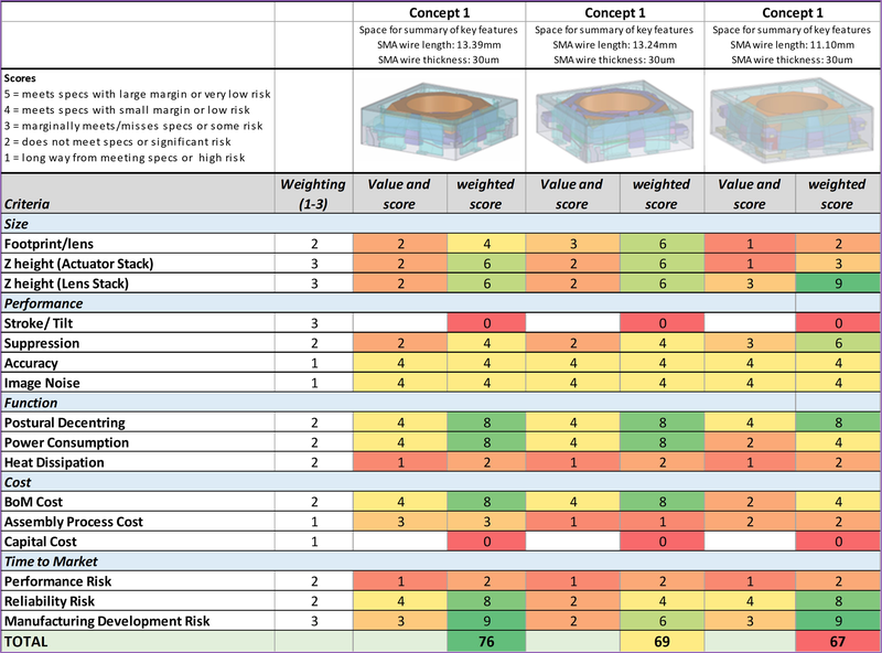
Table 1: Sample of evaluation data for 3 different concepts. In this case, the total weighted score was highest for concept 1.
Build of proof of principle prototypes and components
Before committing further resources, we often create proof of principle prototypes to test critical aspects. We repurpose existing actuator components with simplified, rapid prototyped components to quickly prove principles.
These prototypes help us quickly identify and mitigate major risks, ensuring that the concepts are viable before further development.
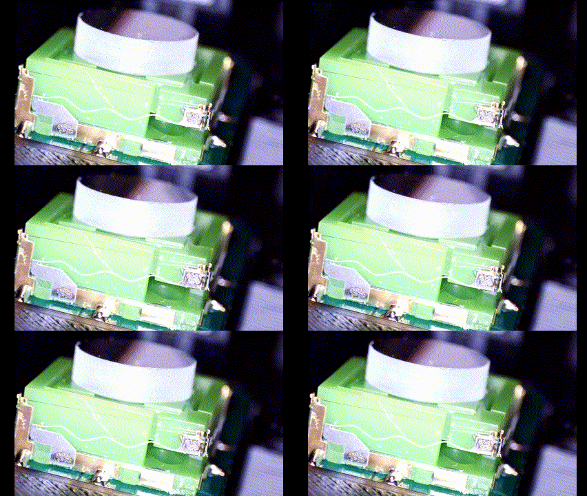 Figure 4: Example of proof of principle prototype testing of a rejected concept.
DFMEA/Risk assessment
Once a concept is selected, we perform a comprehensive Design Failure Mode and Effects Analysis (DFMEA) risk assessment. We bring together engineers from different disciplines to identify potential failure modes and their impacts. We draw on broad experience of the potential failure modes that SMA and miniature actuators can suffer if not designed or built correctly, but also brainstorm and capture new failure modes particular to the design and its requirements. These are then compiled into a DFMEA table, each risk scored, and mitigation actions added. By understanding potential failure modes early, we can design out significant risks, ensuring a more robust final product.
Phase 3: Detailed design of reference actuator
This phase involves creating a detailed actuator design that serves as the basis for performance and reliability testing:
Detailed design
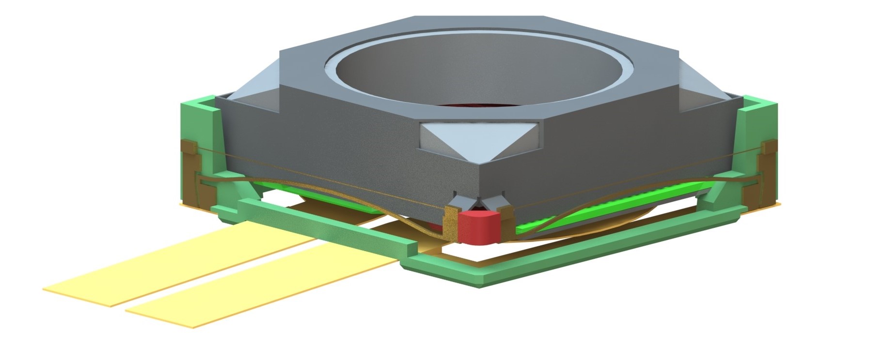
 Figure 5: CAD renders of the chosen design.
Conducting simulations, tolerance analysis, CAD design, and assembly process design to ensure the actuator is ready for production includes designing any necessary tooling. Ensuring that the design is manufacturable and meets all specifications is critical at this stage. Cambridge Mechatronics’ expertise with the types of materials, manufacturing processes, and tolerances typically available to manufacturers in the smartphone actuator industry, means we are perfectly placed to ensure that our unique SMA actuator designs can be converted into high-volume manufacturable products.
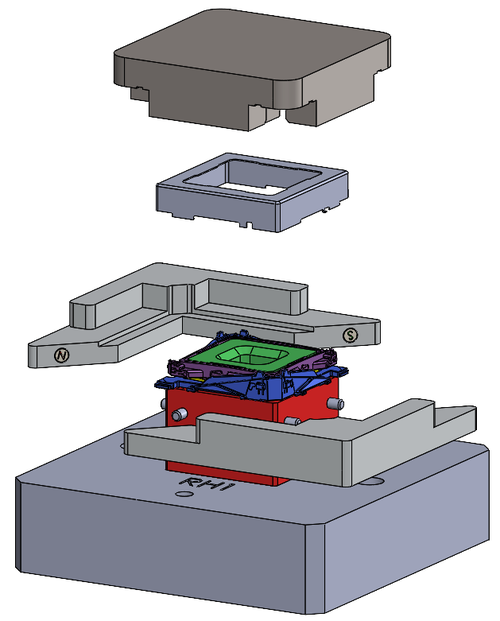 Figure 6: CAD design of tooling for manufacturing the Module Tilt OIS actuator.
Sample actuator build and test
In order to demonstrate the potential of the new product, we typically work with our actuator manufacturing partners or camera makers to build working samples (WS). The first step is for the actuator manufacturer to review our reference design and assembly process and tweak the design to suit their own mass production processes. Once this is done, we work together to jointly build engineering samples (ES). The engineering samples are used to tune our SMA control and then collect performance and reliability which can be provided to handset customers.
Video 1: shaker rig to test suppression capabilities of Module Tilt OIS actuator
For new designs that are stretching the envelope of SMA technology capability CML sometimes choses to insert an extra stage where small numbers of working samples are built in CML’s HQ offices in Cambridge. This approach allows CML to validate key technological aspects, prior to working with actuator makers, that cannot be demonstrated through the proof of principle prototyping process.
Conclusion
At Cambridge Mechatronics, our product design cycle reflects our commitment to innovation using SMA. Our process not only ensures that actuators meet market demands but also sets new standards for performance and reliability in smartphone cameras and beyond. By meticulously following these steps, we continue to lead the industry in developing unique and groundbreaking actuator solutions.
Video 2: Product video of Module Tilt OIS
About Cambridge Mechatronics: Cambridge Mechatronics Limited is a world-leading developer of mechanical, optical, electrical, silicon, and software designs for system-level solutions using its Shape Memory Alloy (SMA) platform technology. ACTUATOR SOLUTIONS based on SMA wire (thin as hair) can be controlled to submicron accuracy. These actuators are particularly suited to applications requiring high precision and force levels, in a fast, compact, and lightweight design.
For more details about SMA technology and Cambridge Mechatronics, please GET IN TOUCH.
